")
")
Our old cat felt a bit lonely after his friend passed away, so we decided to get him some refreshing new company. However, the younglings are eating a whole lot of cat food and this gives me the opportunity to realize a little hardware project with some circuits I had lying around for too long.
THE IDEA
I have a 3D printer, an ESP8266 with WIFI connectivity, a stepper motor with driver and I am an engineer. What could possibly go wrong?
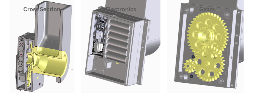
The cat feeder is based on a simple bucket wheel blue print. A reservoir which holds the fodder on top and a cylinder with a pocket to pick up a portion while it rotates. To enjoy the full excitement of being technologically advanced is it imperative that the ESP8266 runs a web socket server to start and stop the feeding from anywhere (especially my couch 😀).
CREATING THE CAD MODEL
Building models for my FDM Prusa Mini comes with some limitations in terms of design if functionality is a focus. They cannot be larger than 180mm in all dimensions and to a) resist the hangry cat and b) be warp free, they have to be of appropriate thickness and size. A good guide for 3D printing model creation is e.g. available from the University of Louisville.
While waiting for all the prints to finish, it is time to take care of the software and electronics
ELECTRONIC HARDWARE
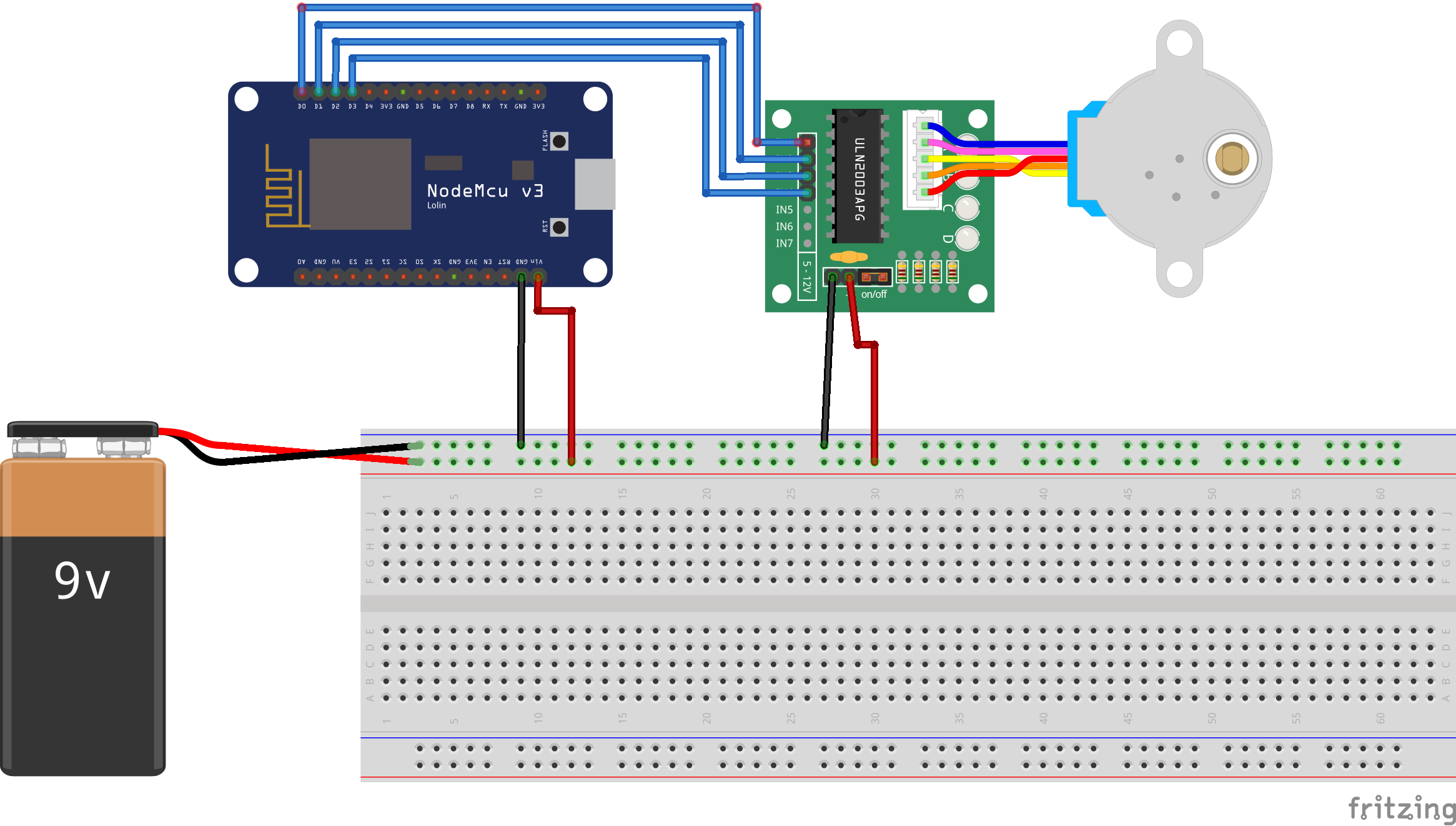
In order to minimize development time and avoid custom designing of PCBs the following four components will be the core of the built:
- ESP8266 NodeMCU board. Its a microcontroller board with integrated WiFi. It can be programmed with the Arduino framework and tools.
- 5V stepper motor
- ULN2003 stepper driver board
- 9V battery
Wiring can be taken from the following diagram. And yes, the 9V battery won't grill the ESP8266 since the datasheet says that you can apply up to 9V even if it says 5V.
CODING FOR NUTRITION
The server side running on the ESP8266 needs some preparation
Installing a file system for the ESP8266
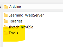
As a prerequisite for this project should you start with installing the LittleFS on the ESP8266. This will enable you to properly structure your project into files as you would do it on an ordinary computer. For details please take a look at the documentation. To actually use it, start with downloading the files and then unpack them into a folder called Tools right in your Arduino directory.
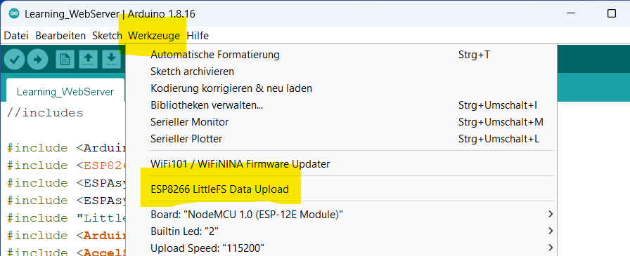
After restarting Arduino you will have the uploader available under the Tools menu.
Last step is to create a folder called data right underneath the folder in which you are going to store your sketch. All files which you want to upload need to be stored into this folder.
Building the homepage
In our case this folder is going to have just one file for starters. This file will be the homepage through which the user is going to interact with the pet feeder.
<!DOCTYPE html>
<html>
<head>
    <title>Cat Feeder V1</title>
    <style type="text/css">
        table {
            border-collapse: collapse;
        }
        td {
            border: 1px solid black;
            padding: 10px;
        }
    </style>
</head>
<body>
    <h1>Cat Feeder V1</h1>
    <table>
        <tr>
            <td>
                <div class="card" style="width: 18rem;">
                    <img class="card-img-top" src="/..." alt="Card image cap">
                    <div class="card-body">
                        <h5 class="card-title">Feeder Status</h5>
                        <p class="card-text" id="stat">Idling</p>
                        <a href="#" class="btn btn-primary" onclick="sendMyMessages()">Start</a>
                    </div>
                </div>
        </tr>
    </table>

    <script type="text/javascript">
        var gateway = `ws://${window.location.hostname}/ws`;
        var websocket = new WebSocket(gateway);

        function getReadings() {
            websocket.send("getReadings");
        }

        // When websocket is established, call the getReadings() function
        websocket.onopen = function(event) {
            console.log('Connection opened');
            getReadings();
        }

        websocket.onclose = function (event) {
            console.log('Connection closed');
        }

        // Function that receives the message from the ESP8266 with the readings
        websocket.onmessage = function (event) {
            console.log(event.data);
            var myObj = JSON.parse(event.data);
            var keys = Object.keys(myObj);

            for (var i = 0; i < keys.length; i++){
                var key = keys[i];
               document.getElementById(key).innerHTML = myObj[key];
           }
        }

        function sendMyMessages() {
          websocket.send("start");
        }
    </script>
</body>
</html>
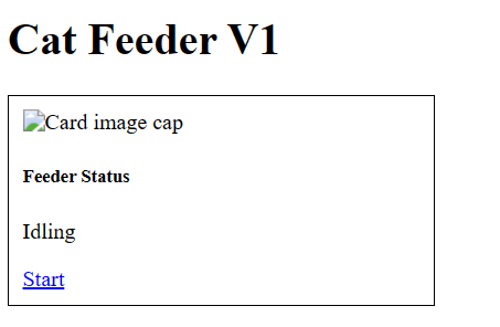
Open the file in a browser of your choice and take a look at the result. A card with a button showing an idling pet feeder. You are free to make it really fancy by adding nice images and CSS magic.
To help you understand the script which is communicating with the server, can you read the docs available at Mozilla or other knowledge bases. A quick, yet detailed enough descripition follows now:
The head tag does two things.
It setst the title "Cat Feeder V1" of the homepage. And the css style of the table is defined here. Setting the border-collapse to collapse shows the border as one solid line instead of two separate ones.
<!DOCTYPE html>
<html>
<head>
    <title>Websocket Table Update</title>
    <style type="text/css">
        table {
            border-collapse: collapse;
        }
        td {
            border: 1px solid black;
            padding: 10px;
        }
    </style>
</head>
Now in the body part of the HTML file happen two things. First a table with only one cell is defined. That cell holds a card. A card is a common design element where you have an image on top followed by some text or information below. We add a button to the text part which will be used to start the feeder by running the sendMyMessages() function which is defined further down int the script part of the code.
<h1>Cat Feeder V1</h1>
    <table>
        <tr>
            <td>
                <div class="card" style="width: 18rem;">
                    <img class="card-img-top" src="/..." alt="Card image cap">
                    <div class="card-body">
                        <h5 class="card-title">Feeder Status</h5>
                        <p class="card-text" id="stat">Idling</p>
                        <a href="#" class="btn btn-primary" onclick="sendMyMessages()">Start</a>
                    </div>
                </div>
        </tr>
    </table>
The very first part of the script simply creates a new WebSocket() object. The variable gateway contains the IP adress of the homepage, respectively our server.
var gateway = `ws://${window.location.hostname}/ws`;
var websocket = new WebSocket(gateway);
When the connection to the server is established the onopen function executes the getReadings() function which will send the command to the server which triggers it to send data back to the webpage. The console output is just for information to track what happens.
function getReadings() {
            websocket.send("getReadings");
        }

        // When websocket is established, call the getReadings() function
        websocket.onopen = function(event) {
            console.log('Connection opened');
            getReadings();
        }
Once the connection is closed the console will log that as well
 websocket.onclose = function (event) {
            console.log('Connection closed');
        }
Now, we have requested data from the server which will send data constantly. This data needs to be displayed in the respective elements of our HTML file. Since the server is sending JSON we are simply parsing it and write the result to the HTML elements. A little logging is done as well.
 // Function that receives the message from the ESP8266 with the readings
        websocket.onmessage = function (event) {
            console.log(event.data);
            var myObj = JSON.parse(event.data);
            var keys = Object.keys(myObj);

            for (var i = 0; i < keys.length; i++){
                var key = keys[i];
               document.getElementById(key).innerHTML = myObj[key];
           }
        }
To tell the server that we want to start the stepper motor are we using the sendMyMessages() function which simply sends the text start once the start button is pressed.
function sendMyMessages() {
    websocket.send("start");
}
The server
The last step to get the system running is to program the server. To do so open your Arduino IDE and create a new sketch with the following code.
//includes

#include <Arduino.h>
#include <ESP8266WiFi.h>
#include <ESPAsyncTCP.h>
#include <ESPAsyncWebServer.h>
#include "LittleFS.h"
#include <Arduino_JSON.h>
#include <AccelStepper.h>

AsyncWebServer server(80);
AsyncWebSocket ws("/ws");

JSONVar data;

unsigned long lastTime = 0;
unsigned long timerDelay = 3000;


AccelStepper myStepper(AccelStepper::FULL4WIRE, 16,4,5,0);
const int stepsPerRevolution = 49152;
bool newRequest = false;

void activate_feeder()
{
  //ToDo start the motor
  myStepper.setSpeed(400);
  myStepper.setAcceleration(40);
  myStepper.move(stepsPerRevolution);

  while (myStepper.currentPosition() != myStepper.targetPosition())
  {
      myStepper.run();
      yield();
  }

  send_status_update();
}

void send_status_update()
{
  data["stat"] = String("I am turning");
  String jsonString = JSON.stringify(data);
  ws.textAll(jsonString);

  Serial.println("Motor turining");
}

void handleWebSocketMessage(void *arg, uint8_t *data, size_t len)
{
  AwsFrameInfo *info = (AwsFrameInfo*)arg;
  if (info->final && info->index == 0 && info->len == len && info->opcode == WS_TEXT)
  {
    data[len]=0;
    String message = (char*)data;
    if (strcmp((char*)data, "start") == 0)
    {
      send_status_update();
      newRequest = true;
    }
  }
}

void onEvent(AsyncWebSocket *server, AsyncWebSocketClient *client, AwsEventType type, void *arg, uint8_t *data, size_t len) {
  switch (type) {
    case WS_EVT_CONNECT:
      Serial.printf("WebSocket client #%u connected from %s\n", client->id(), client->remoteIP().toString().c_str());
      break;
    case WS_EVT_DISCONNECT:
      Serial.printf("WebSocket client #%u disconnected\n", client->id());
      break;
    case WS_EVT_DATA:
      handleWebSocketMessage(arg, data, len);
      break;
    case WS_EVT_PONG:
    case WS_EVT_ERROR:
      break;
  }
}


void setup() {

  //Set stepper parameters
  myStepper.setMaxSpeed(400);
  myStepper.setAcceleration(40);
  myStepper.setSpeed(400);

  // put your setup code here, to run once:
  Serial.begin(115200);
  WiFi.begin("YOUR_WIFI_NAME_HERE", "YOUR_PASSWORD_HERE");

  //Track until the WiFi connection is established
  Serial.println("\nWaiting for connection");
  while (WiFi.status() != WL_CONNECTED)
  {
    Serial.print(".");
    delay(500);
  }

  Serial.println("\nConnection established");
  Serial.println("\nMy IP is: ");
  Serial.println(WiFi.localIP());

  ws.onEvent(onEvent);
  server.addHandler(&ws);

  //Start little FS
  if (!LittleFS.begin()) {
    Serial.println("An error has occurred while mounting LittleFS");
  }
  else{
   Serial.println("LittleFS mounted successfully");
  }

  // Return Landingpage at first connection
  server.on("/", HTTP_GET, [](AsyncWebServerRequest *request) {
    request->send(LittleFS, "/index.html");
  });

  server.serveStatic("/", LittleFS, "/");

  server.begin();
}

void loop() {

  if ((millis() - lastTime) > timerDelay) {
    Serial.print("\nNothing to do");
    lastTime = millis();
  }
  else if (newRequest == true)
  {
    activate_feeder();
    newRequest = false;
  }

  ws.cleanupClients();
}
Code breakdown
As usual the first part of the Arduino file contains all the necessary include files, variable and function declarations.
#include <Arduino.h>
#include <ESP8266WiFi.h>
#include <ESPAsyncTCP.h>
#include <ESPAsyncWebServer.h>
#include "LittleFS.h"
#include <Arduino_JSON.h>
#include <AccelStepper.h>
The includes are a necessity for all the stuff we are going to use later on.
AsyncWebServer server(80);
AsyncWebSocket ws("/ws");
It gets interesting when we create an instance of a webserver which is going to listen on port 80 and an instance of a websocket object. Please note that we are using the asynchronous servers and websockets to allow multiple connections at a time.
JSONVar data;
The variable data is going to be used for exchange of information between server and client.
unsigned long lastTime = 0;
unsigned long timerDelay = 3000;
lastTime and timerDelay define how frequent the program is going to look for new commands from the client.
AccelStepper myStepper(AccelStepper::FULL4WIRE, 16,4,5,0);
myStepper sets all the data the used motor requires to work. FULL4WIRE means that it is using four connections and the following numbers define the pins of the ESP which are connected to the stepper driver.
const int stepsPerRevolution = 49152;stepsPerRevolution are defined by the number of steps the motor has per revolution multiplied with the gear ratio.
bool newRequest = false;The boolean newRequest is used to monitor if the client sent a new request and is set to false which means that we are doing nothing after the program starts running.
void activate_feeder()
{
  //ToDo start the motor
  myStepper.setSpeed(400);
  myStepper.setAcceleration(40);
  myStepper.move(stepsPerRevolution);

  while (myStepper.currentPosition() != myStepper.targetPosition())
  {
      myStepper.run();
      yield();
  }

  send_status_update();
}

void send_status_update()
{
  data["stat"] = String("I am turning");
  String jsonString = JSON.stringify(data);
  ws.textAll(jsonString);

  Serial.println("Motor turining");
}
Calling the function activate_feeder() will start the motor and keep it running until a complete rotation is finished. You can set the acelleration and speed the motor is running with. the function also calls send_status_update() a function which uses the JSON variable data to send the message "I am turning" to the client.
void handleWebSocketMessage(void *arg, uint8_t *data, size_t len)
{
  AwsFrameInfo *info = (AwsFrameInfo*)arg;
  if (info->final && info->index == 0 && info->len == len && info->opcode == WS_TEXT)
  {
    data[len]=0;
    String message = (char*)data;
    if (strcmp((char*)data, "start") == 0)
    {
      send_status_update();
      newRequest = true;
    }
  }
}

void onEvent(AsyncWebSocket *server, AsyncWebSocketClient *client, AwsEventType type, void *arg, uint8_t *data, size_t len) {
  switch (type) {
    case WS_EVT_CONNECT:
      Serial.printf("WebSocket client #%u connected from %s\n", client->id(), client->remoteIP().toString().c_str());
      break;
    case WS_EVT_DISCONNECT:
      Serial.printf("WebSocket client #%u disconnected\n", client->id());
      break;
    case WS_EVT_DATA:
      handleWebSocketMessage(arg, data, len);
      break;
    case WS_EVT_PONG:
    case WS_EVT_ERROR:
      break;
  }
}
handleWebSocketMessaging() will deal with incoming messages from the client. As defined in the client side script we will be cheking for the signal word "start". Once this signal word is found in the message the variable newRequest will be set to true which sets off the motor as we will see later on in the loop part of the Arduino file.
The onEvent() function handles all standard events that might occur in the websocket communication. To keep things easy are we taking care of connection and disconnection by a simple print command which can be seen in the Arduino console and the previously described event of data coming from the client.
First Test
The first assembly of the housing and the gears should now be ready to move for the first time and reveal whatever went wrong in the design